Reliability Concepts Blog
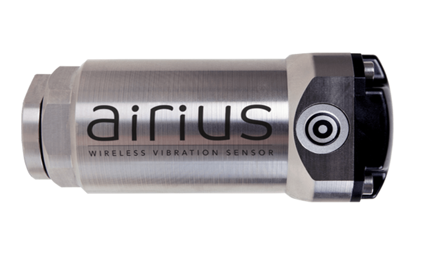
Not all
vibrations sensors are equal and knowing how to select, install and use a
vibration sensor is one of the fundamentals skills first learned when training
as a vibration analyst. Simply put, if
the sensor is tone deaf to the vibration you need to monitor; it will not
detect the fault when it occurs. This applies equally to low frequencies and
high frequencies.
If you visit any website from any accelerometer supplier, you will see a vast selection of accelerometers to suit every application. When wired sensors are used there is a sensor selection process that takes the application into consideration.
When using either wired or wireless monitoring, considerations such as rotational speed, bearings, environment, temperature, mounting, and other factors MUST be evaluated to effectively monitor the selected machinery. Failure to do so will result in unreliable data, false and missed alarms and failures.
This is why the SPM AIRIUS wireless sensor comes in a variety of configurations that are suited to many applications and why more are in development. Also when the application exceeds the capability or practicality of a wireless sensor there is full compatibility with the Leonova Online and the Diamond Portables. Also you have the choice of Condmaster Ruby 2020 for local or server data management and analysis as well as Condmaster.net for cloud based analytics.
Features of AIRIUS Vibration Sensors:
- Measures triaxial vibration and temperature
- 6 versions for a variety of appications.
- Envelope measurement capabilities.
- Different vibration measurements on one sensor.
- Communicates directly to WIFI 802.11n/g.
- User defined number of time-based daily measurements.
- Compatibility with Intellinova® online system, portable Leonova® Diamond and Emerald instruments.
- Compatibility means you only need one system, Condmaster 2020 Ruby, for wired, wireless, portable, remote, multi-site, and more.
- From basic alarming to complex analysis, condition monitoring, and vibration analysis has never been this versatile, affordable, and this easy.
AIRIUS Sensor Options:
- AIR01-01-Airius 10-1000 Hz
- AIR01-10-Airius 2-1000 Hz / 10-5000 Hz
- AIR01-01-EX Airius EX 10-1000 Hz for explosive environments.
- AIR01-10-EX Airius EX 2-1000 Hz / 10-5000 Hz for explosive environments.
- AIR02-01 Airius 10-1000 Hz Wireless externally powered.
- AIR02-10 Airius 2-1000 Hz / 10-5000 Hz externally powered.

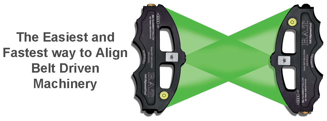
- The B.A.T. Is Easy: Dual Lasers Make Correcting Misalignment Easy
- The B.A.T. Is Fast: Correcting Misalignment Is Intuitive And Fast, Technicians Like To Use This Tool.
- The B.A.T. Is Versatile: Designed To Work On Almost Every Application.
- The B.A.T. Is Amazingly Accurate: The Patented Dual Lasers & Glowline Targeting System Make The B.A.T. Super Accurate.
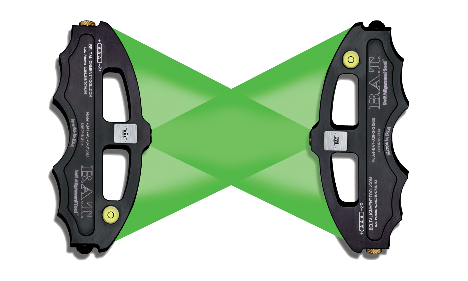
Fact: Belt misalignment often goes uncorrected because other belt alignment tools and techniques are confusing, and the results may be inaccurate.
Fact: You can eliminate problems with belt driven machinery in your operation by using the Patented B.A.T. Belt Alignment Tool®.
Why is the B.A.T. the Best Belt Alignment Tool Made?
1. Easy: Dual Lasers Make Correcting Misalignment Easy.
2. Fast: Correcting Misalignment is Intuitive and Fast, Technicians Like to Use this Tool.
3. Versatile: Designed to Work on Almost Every Application.
4. Accurate: The Patented Dual Lasers & Glowline Targeting System Make the B.A.T. Super Accurate.
5. Multi Functional: Check Base Level, Flatness, Align More than Two Pullies at Once, Foundation Layout and More!

When deploying a wireless vibration monitoring system there is a honeymoon phase when things go as planned. Inevitably something goes askew and reality enters the picture. It may be due to a wireless monitored asset that failed and was not detected. It could be the need to deploy a critical application where there is no access, or needs the capability to analyze vibration values beyond 1kHz and may be required to send data frequently, such as every 5 minutes or more.
These issues can be well beyond the capability of most wireless vibration sensors. Also, sending large amounts of data can deplete a battery in days, weeks, or months. If the wireless monitoring system does not support a variety of solutions, you would need to invest in an additional system to meet this single need. Often the only solution is to invest in a non-compatible system that supports wired online vibration monitoring.
SPM has taken these issues into account by developing the diverse Condmaster Ruby 2020. The Condmaster Ruby 2020 platform has affordable configurations for every vibration analysis application. Most recently, development of the externally powered AIRIUS Tri-Axial wireless vibration sensor means you can get full spectrums, waveform and temperature data as frequently as every minute for years without servicing the sensor or replacing batteries.
SPM™ is far more than the proven Shock Pulse Method. SPM™ is now a complete vibration analysis platform. With the Condmaster Ruby 2020, Insen Online Systems, Diamond Vibration Analyzer / Data Collector and ARIUS Wireless sensors. SPM has developed a highly comprehensive suite of products designed to work as one cohesive system with Condmaster 2020 as the central analytical engine. The benefit to the end user is that you do not need to have several iterations of condition monitoring systems to accomplish vibration analysis monitoring of every application. With performance enhancements on the horizon there currently 6 different versions of the innovative AIRIUS™ Wireless vibration sensor that meet price and performance objectives for all applications. Contact us for more information.
sales@reliabilityconcepts.com * 517-278-8057
AIR01-01 Airius 10-1000 Hz Wireless Vibration Sensor
AIR01-10 Airius 2-1000 Hz / 10-5000 Hz Wireless Vibration Sensor
AIR01-01-EX Airius EX 10-1000 Hz Wireless Vibration Sensor for explosive environments.
AIR01-10-EX Airius EX 2-1000 Hz / 10-5000 Hz Wireless Vibration Sensor for explosive environments.
AIR02-01 Airius 10-1000 Hz Wireless Vibration Transducer, externally powered.
AIR02-10 Airius 2-1000 Hz / 10-5000 Hz Wireless Vibration Sensor, externally powered.
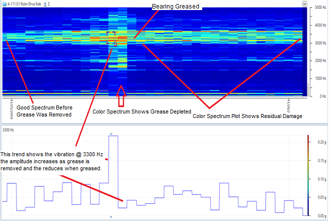
Why wireless sensor Fmax is Critical.
SPM™ AIRIUS™ 5kHz Wireless Vibration and Condmaster Ruby Dry Bearing Test.
Lack of lubrication is a major cause of bearing damage & bearing failure. Therefore, it is critical for vibration sensors to be able to detect the higher frequency vibration resulting from lack of lubrication, which is generally far above 1kHz. We tested the 5kHz ARIIUS™ wireless vibration sensor from SPM™. The following data are from our dry bearing test. This test simulates a dry bearing fault developing and then the re-lubrication event. Please see the following test parameters, results and graphics.
1. Bearing: SKF 6205
2. RPM: 2100
3. Motor: HP 1.5
4. Machine Type: Test Stand with Belt Driven Overhung Rotor.
Test Procedure:
Data was taken over a period of 2.5 hours. The bearing was a new pillow block mounted 6205. The seals were removed to accommodate removal of the grease during the test.
Step 1. Test Rotor ran for 30 minutes with normal grease amount.
Step 2. After 30 minutes the grease was gradually removed while running.
Step 3. After a nominal amount of grease was removed the rotor ran until the residual lubrication was depleted.
Step 4. Complete depletion of the lubricant was achieved and resulting plots are shown.
Step 5. In this step grease was reintroduced into the bearing.
Results:
The following illustrations clearly show the trending amplitudes from depletion of the lubricant. This is followed by a sudden increase in vibration once the bearing is totally void of any trace of lubrication. This event is followed by the re-introduction of grease to the bearing, the vibration levels instantly reduced, however vibration levels are elevated from the baseline by .192g’s. The vibration spectrum and color spectrum plots easily show the event cycle and the increased vibration from lack of lubrication. If you look at the spectrum plots the bottom spectrum shows the 1kHz cut off point. If the sensor used had an Fmax of 1kHz the lack of lubrication event and resulting damage is not detected as the primary frequencies are around 3.3kHz.
1. SPM Colored Spectrum™ Plot
2. g’s rms overall plot.
3. Spectrum Plots
1. Colored Spectrum
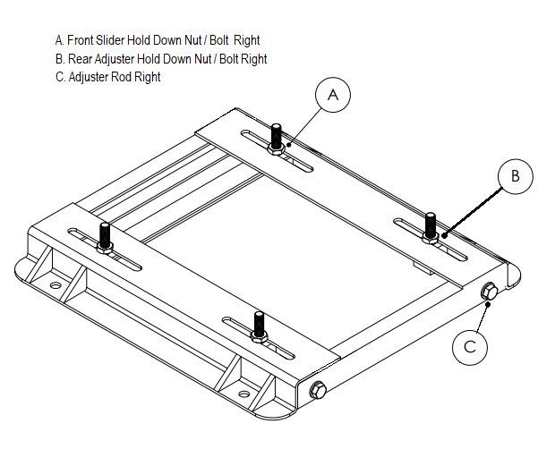
Adjustable motor bases and rails are available in a variety of sizes that accommodate most motors. These bases are an easy and great solution as they simplify installation and offer adjustments for alignment and tensioning.
Adjustable motor bases are very real problems for maintenance and mechanical professionals. The base becomes impossible to adjust, nuts freeze up, bolts seize, rails crack and ultimately the base completely fails.
Belt installation is often done improperly because the base bolts are bent, locked and seized, they cannot be loosened, and the motor can’t be moved. As a result, the belts are rolled on to the pulley!
This also impacts reliability because belts are left misaligned, mounting bolts are loose, metal fatigue results and the motor and driven equipment vibrate excessively.
The most common reason for seized or frozen bolts, fatigue cracks and broken a motor base is, improper adjusting and tightening of the motor. If this procedure is not followed the motor mounting bolts will bend when tightened! Once bent these bolts lose tension and will ultimately fail.
Here are few tips on how you can make your motor bases more reliable and stand the test of time.
Adjustable and slide motor base tensioning procedure.
1. Make sure the base and slide rails are clean and free of debris.
2. Make sure the base rails are flat to each other. Use the B.A.T. Belt Alignment Tool with disc targets to check flatness.
3. Lubricate the tensioning rods with a small amount of grease. This will reduce friction on the tensioning nut that holds the motor hold down bolt.
4. Set the motor.
5. Install the nuts on all 4 motor hold down bolts loosely. This is critical and will allow the motor to slide easily without damaging the hold down bolt threads.
6. Begin to tension the belts by alternating the turning of the tensioning rods left to right.
7. Observe the belt tension and adjust to the recommended tension.
8. Tighten the FRONT motor hold Down nuts FIRST! Alternate tightening left to right.
9. Stop tightening the FRONT nuts when they are tight enough to prevent sliding of the motor.
10. Ease and loosen the tensioning rods on the back feet of the motor. There should be enough torque on the front bolts to prevent the motor from being pulled forward by the belt tension.
11. The rear tensioning bolts should be loose and have clearance in the motor foot bores.
12. Tighten the rear motor feet hold down bolts, alternating left to right.
13. Tighten the nuts enough to prevent the motor from moving.
a. This procedure has pulled the motor down to the base and has trued the bolts in the motor foot bores. As the motor is pulled down, the belt tension increases slightly.
b. Recheck the belt tension again and re-adjust the motor by slightly tightening the adjusting rods, loosening the hold down bolts and repeating steps 6 through 13.
14. Check alignment with the B.A.T. Belt Alignment Tool and adjust as needed.
15. Confirm proper tension.
16. Tighten the nuts as described in step 8-12 to specified torque using a torque wrench.

SPM Instrument AB, leading worldwide provider of condition monitoring technology and products, today announces the release of AiriusTM, a range of wireless vibration sensors for remote monitoring of industrial equipment.
Providing warning of vibration-related problems as well as gear and bearing faults, Airius is a wireless, battery-powered sensor ideal for remote condition monitoring of standard production equipment such as pumps and fans. Designed and manufactured by SPM Instrument, the sensors build on fifty years of experience in developing reliable and industry-leading solutions for condition monitoring.
Industry -leading measurement technology
Airius is a MEMS type sensor with digital output, measuring triaxial vibration and temperature. The sensor currently comes in two versions; one measuring in the 10-1000 Hz frequency range, the other between 2-1000 Hz and 10-5000 Hz with envelope measurement capabilities. Airius supports several different vibration measurement assignments per sensor, with a user-defined number of time-based daily measurements. The signal processing algorithms and calculation routines used are the same as in the high-end Intellinova® online system and the sophisticated portable Leonova® Diamond and Leonova® Emerald instruments.
Easy integration and trouble-free use
The Airius sensors have a compact design, with an energy-saving communication protocol. The careful design and optimal choice of battery technology ensure years of troublefree use and stable monitoring. In idle state, sensor power consumption is extremely low. Using the well-established and stable WiFi data transfer technology, Airius is an easy-to-implement solution that works well within existing IT environments. The IP69 rating makes Airius SPM’s most durable sensor, suitable for even the most demanding environments.
Straightforward installation and effortless setup
Airius does not require any supplementary equipment besides W iFi routers. The sensors have the shortest response times in the segment, making installation and commissioning straightforward and fast. The SPM Connect app, downloadable for Android and iOS devices, is used to configure the necessary communication parameters to connect to the database. REST API support allows other devices or process control systems to retrieve vibration data from the sensor.
The Airius sensors and SPM Connect app will be available for delivery and download from the week starting June 17th, 2019. Ex versions for potentially explosive environments will be released in the fall of 2019.
